Ibrahim Alrashed
Computational designer driving closed-form subdivision and lattice mathematics into cast concrete and cut timber.
Biography
I grew up around things being built — timber, concrete, the tolerance of a hand-cut joint — and I now write the algorithms that decide how they are shaped.
My practice sits where computational geometry meets physical fabrication. I work almost entirely in Houdini and VEX, building generative systems in which form isn't drawn but derived: a subdivision rule, a lattice tiling, a projection function, each carrying a small set of weights I tune until the geometry becomes something I didn't predict. What holds my attention is the moment mathematics stops being notation and becomes matter — when a recursive subdivision has to survive a 3D-printed sand mould, a steel cage and a concrete pour, or when a hexagonal lattice has to be collapsed onto a funnel surface and then flattened into profiles a three-axis router can actually cut.
I also work with my hands: CNC woodwork, furniture, kumiko joinery, building formwork. That side keeps the algorithms honest. A rule that produces a beautiful mesh but an unbuildable joint isn't finished.
I live and work in Syria, and most of what I've built stands in Aleppo, Tartus and Latakia. Working here means designing for the fabrication that is actually available rather than the fabrication a software tutorial assumes, and that constraint has shaped the work more than any aesthetic preference has.
Portfolio and contact
Series Narrative
Both of these works began the same way: with an equation I could not picture.
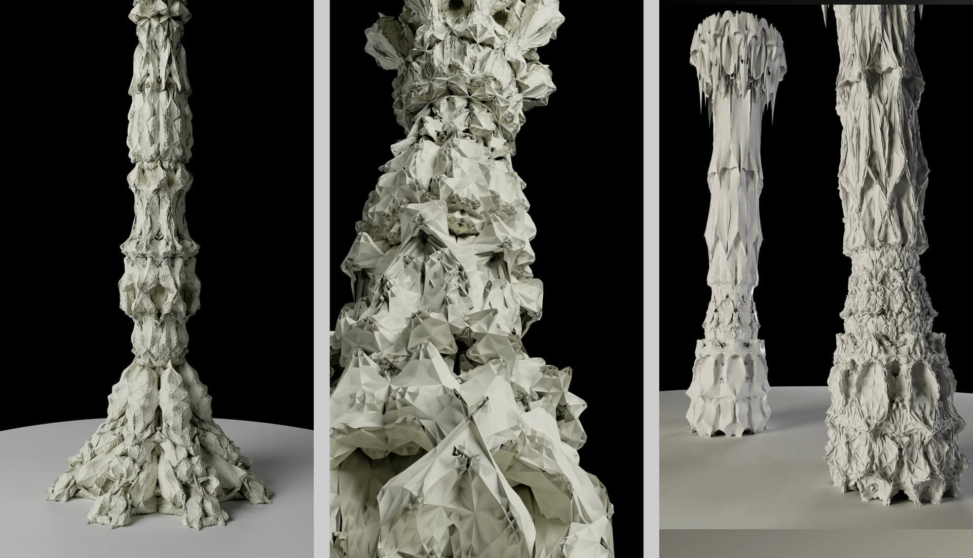
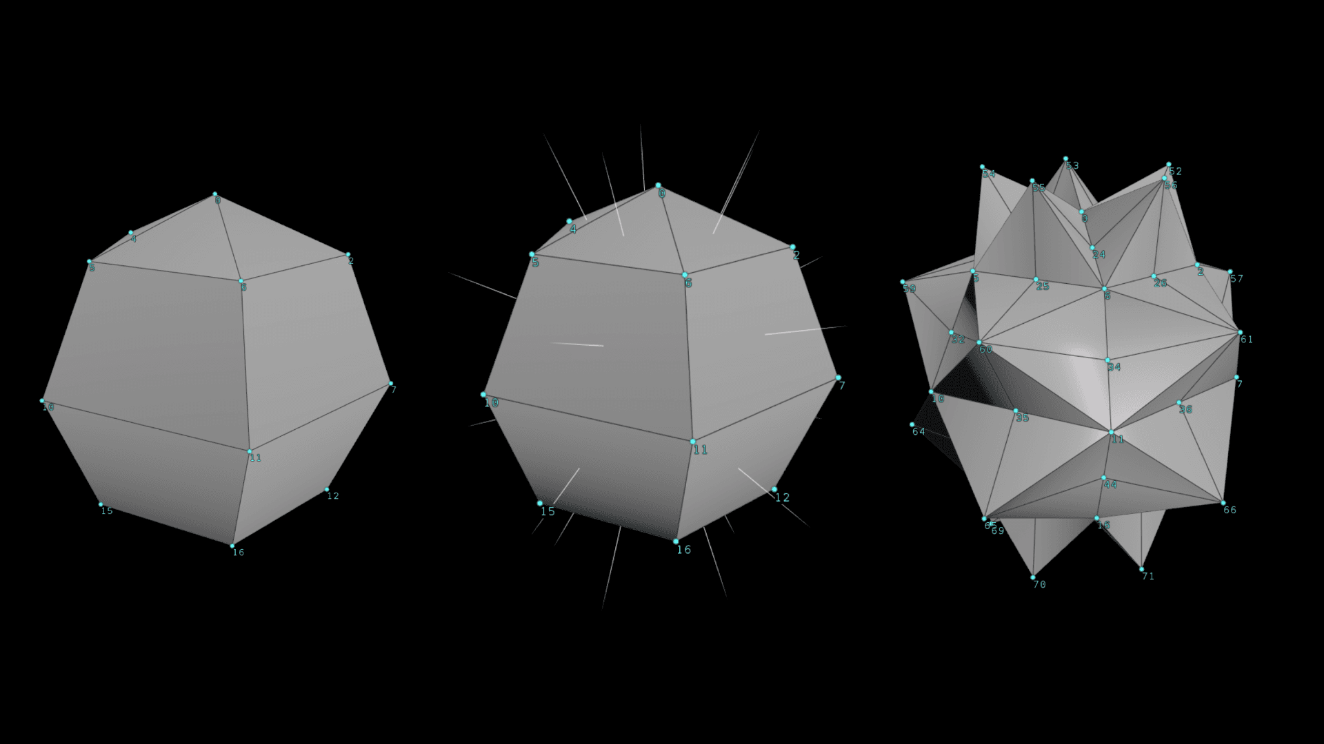
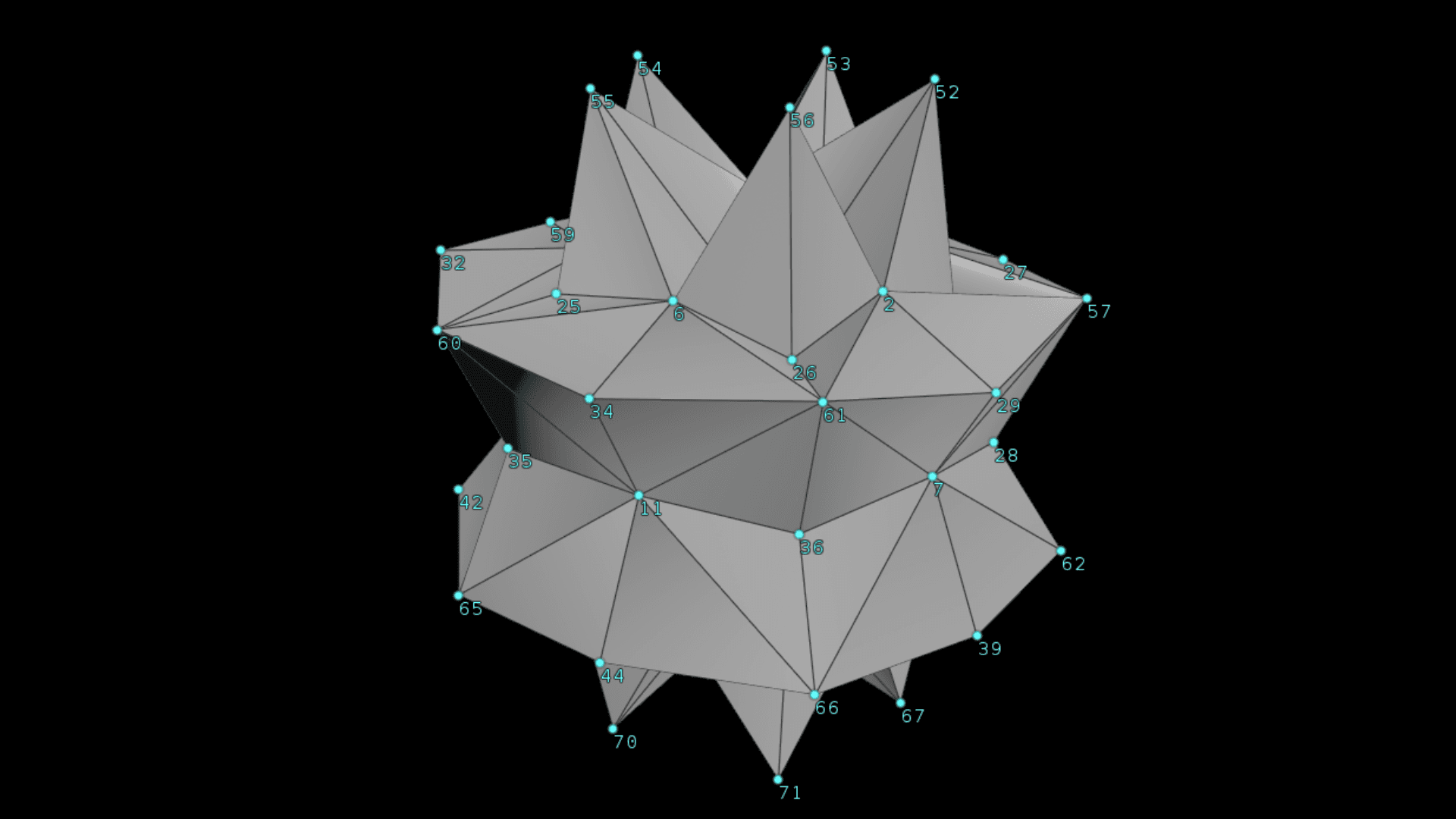
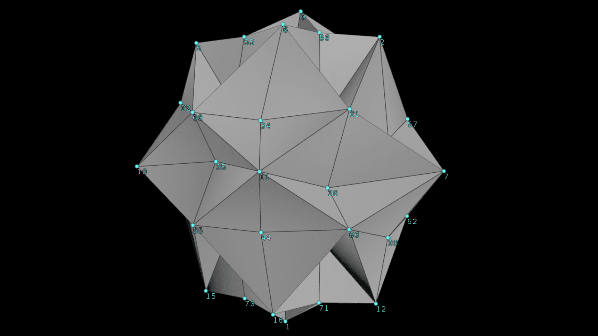
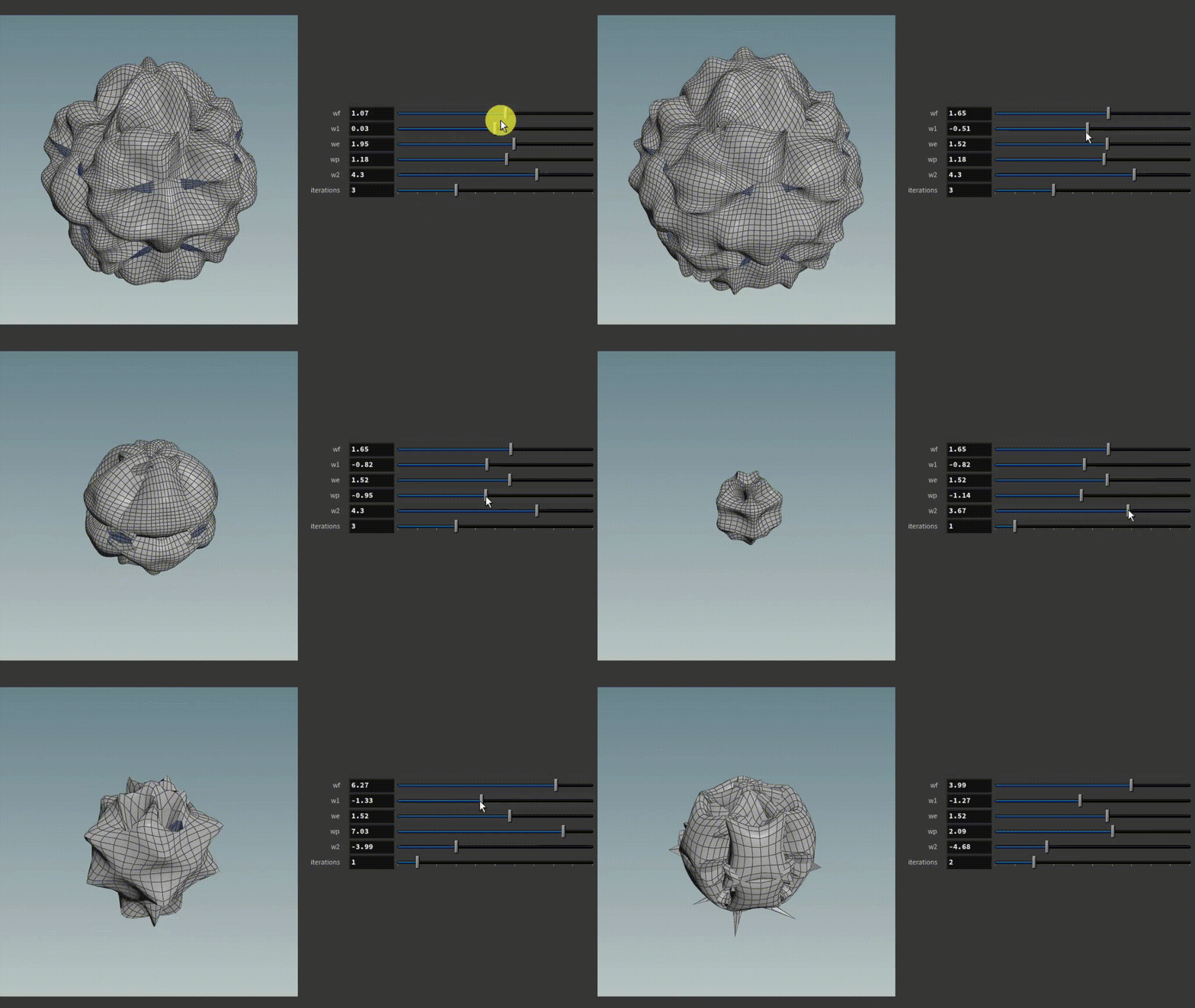
I don't sketch forms. I write a rule and then find out what it makes. In the Isaac Columns the rule is a Catmull-Clark subdivision with five extra weights bolted onto it — each new face point, edge point and vertex is not only averaged from its neighbours but pushed outward along its own normal by an amount I control. Classical subdivision smooths a shape toward a limit surface. Weighting it this way does the opposite: the surface refuses to settle, and every iteration grows a finer order of ornament out of the one beneath it. Seven columns came out of a single eight-sided primitive and five numbers.
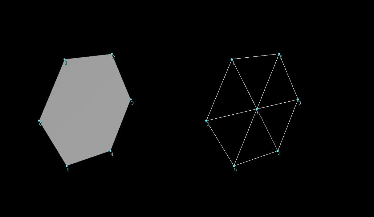
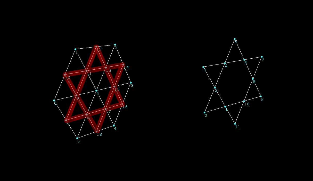
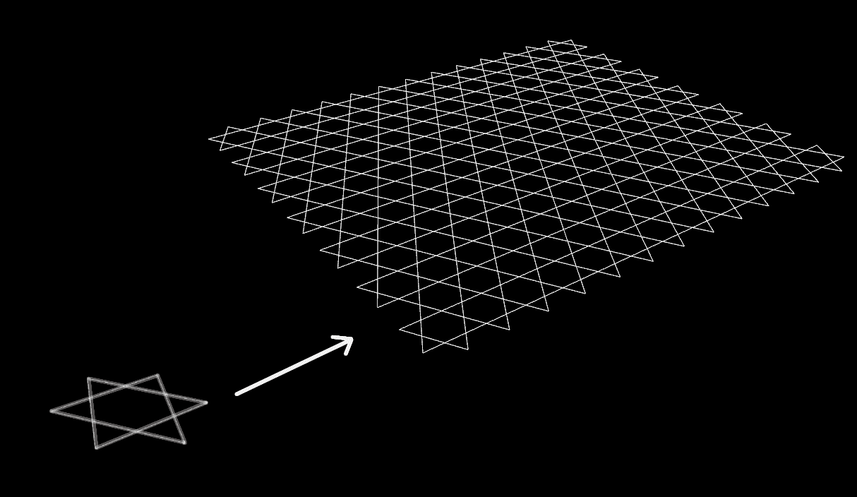
The Tartus canopy starts from a hexagon instead. Connect its corners to its centroid, inscribe smaller triangles, delete what is surplus, and a hexagram is left; tile that on two lattice vectors and you have a Kagome grid — the same interlace I had already cut by hand in kumiko joinery, now at the scale of a roof. Then I remapped every lattice point onto a funnel through an exponential decay, and the flat pattern collapsed into supports.
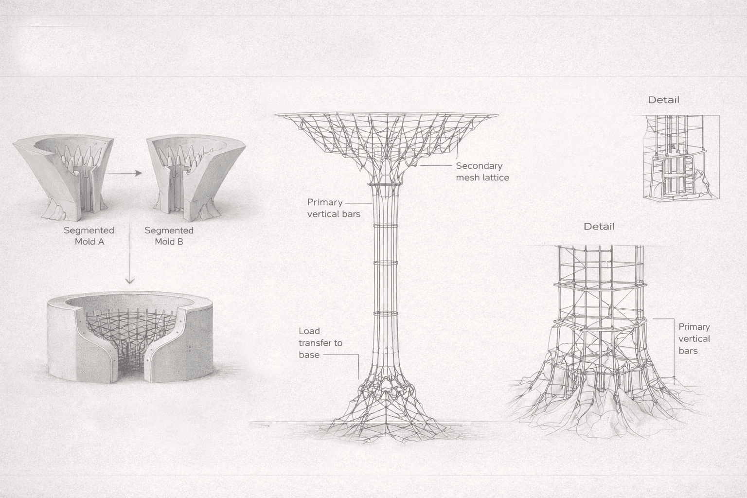
What connects them is not geometry but the pour and the cut. An algorithm is free; a 3D-printed sand mould has to be segmented so it can be assembled around a steel cage, and concrete has to survive the release. A curved timber member has to be a profile a three-axis router can actually reach. Half of the design work in both projects was the translation — the point where an abstraction either becomes a physical object or stays a render.
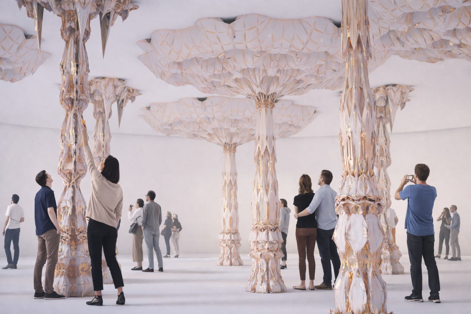
Isaac Columns
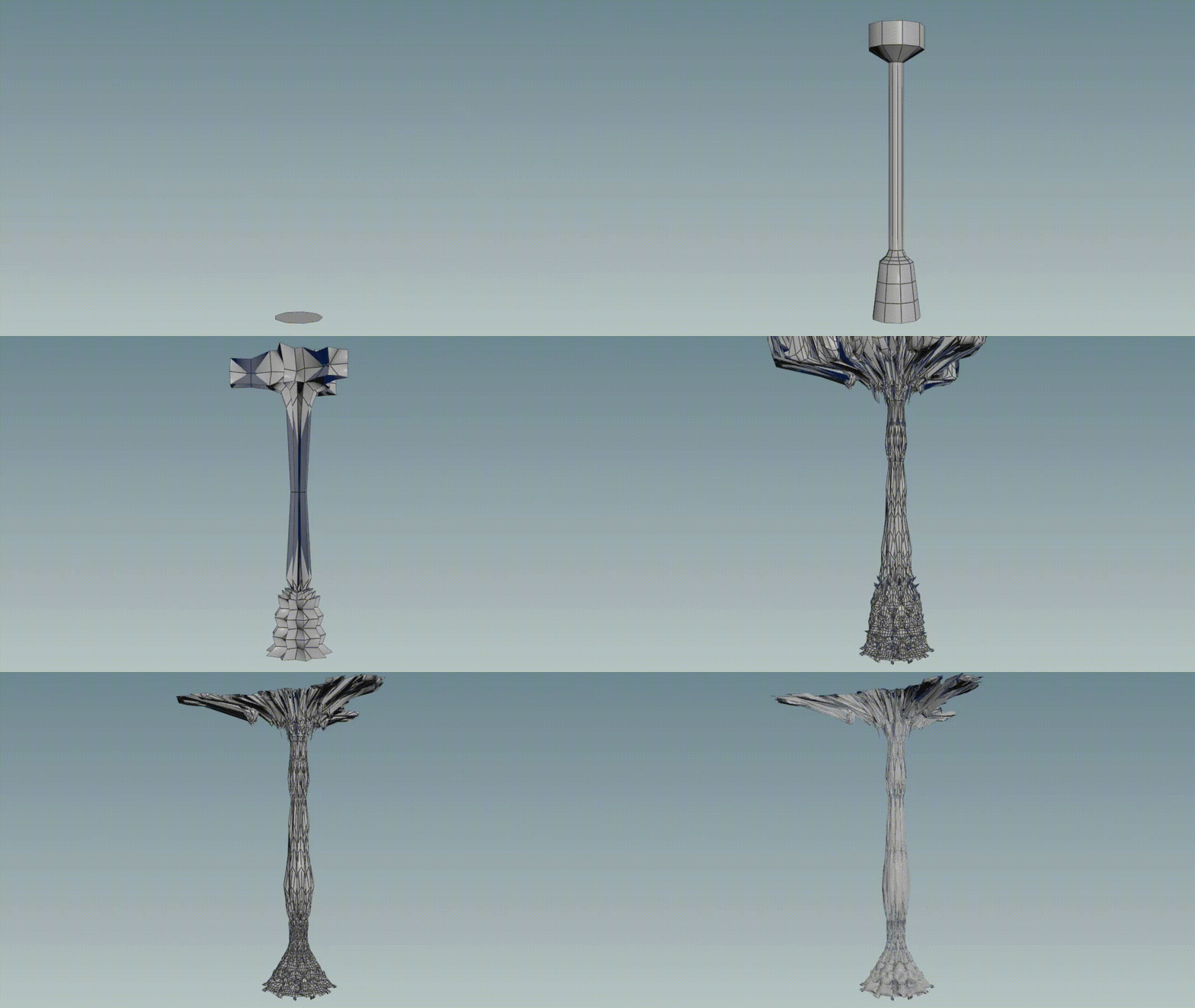
A family of seven cast concrete columns generated by one parametric system. The base geometry is a simple primitive; the surface articulation is produced entirely by recursive weighted Catmull-Clark subdivision, where five independent weights displace the face, edge and vertex points outward at each iteration rather than relaxing them inward. Changing those five values — or the iteration count alone — yields a different column, so no two in the set repeat.
Each column was cast rather than printed. The moulds were segmented and produced on a 3D sand printer, assembled around a welded steel reinforcement cage, filled with concrete and left to cure before release
Medium / materials
Dimensions
Count
7
Algorithm
Weighted Catmull-Clark subdivision
Fabrication
3D sand printing / moulding
Software
-R9F82jgMUIu4ST7FUh5x0fr8ZQ8B8q.png&w=3840&q=75)
Tartus Train Station Kagome Canopy
From Hexagram Tiling to Funnel Shell
A timber canopy over the passenger waiting area of Tartus train station, 5.3 m at its highest point. The structure derives from a flat Kagome lattice: a hexagon subdivided to its centroid, reduced to a hexagram, then tiled across a plane on two lattice vectors. That planar grid is mapped onto a funnel surface in cylindrical coordinates, with an exponential decay function driving the vertical collapse — so the roof plane and its supports are the same continuous lattice, not a roof resting on columns.
Every member is doubly curved and individually unique. The geometry was unrolled into flat profiles and cut on a 3-axis CNC router from Oak, then assembled on site.
Medium / materials
Dimensions
Algorithm
Geodesic projection
Fabrication
3-axis CNC router
Software
Process Documentation
Sketches, working drawings and process stills from both works.
Subdivision growth — simple primitive to finished column profile. Parameter study — sweeping the five subdivision weights. 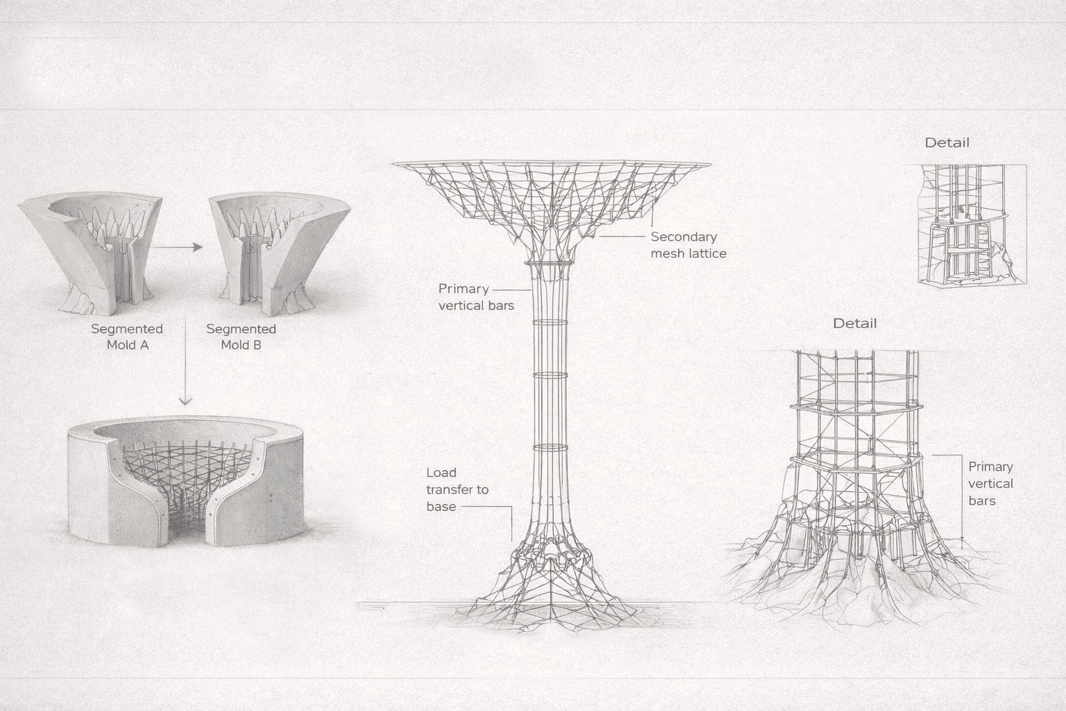
Working drawing — segmented sand moulds, reinforcement cage and load transfer to base. 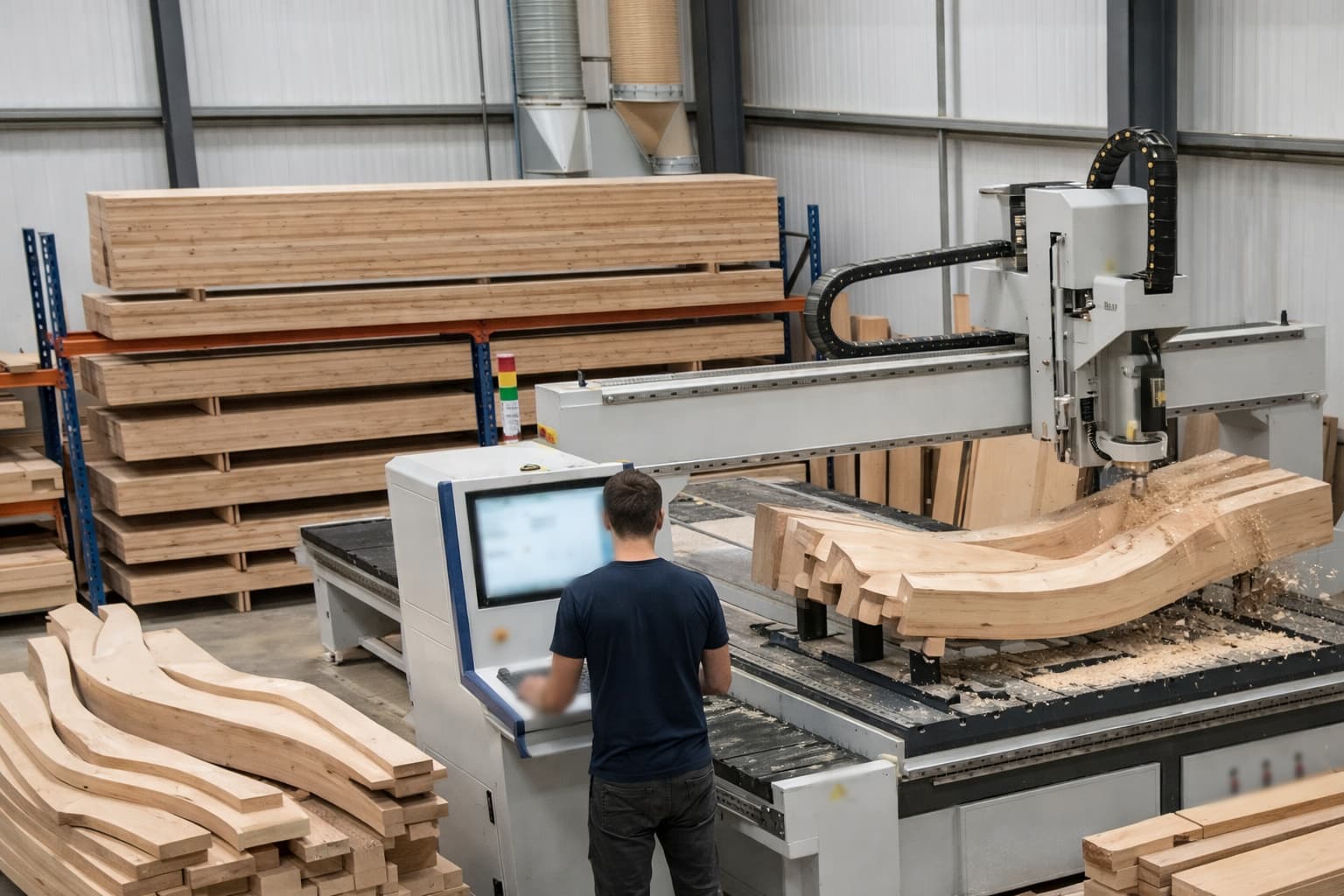
3-axis CNC router cutting the curved timber members.